Annotate
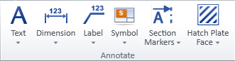
On the Drafting tab, the Annotate group includes the following tools.
While using annotation commands, you can visit Plant Modeller work views by pressing the Tab key. This has the following advantages:
-
If annotating a drawing view, you can, for example, select the object to be labeled or the point to be dimensioned from a 3D view.
-
If annotating a page, jumping to a work view starts the Query Object command, which enables, for example, taking measurements and opening the Properties pane.
Text
You can annotate drawings by inserting multi-line text strings that provide some information about the model or the document itself.
You can insert and modify texts with the tools in the Text menu. You can also modify texts with the generic tools described in Modify.
Texts have the properties described in Text Properties. Administrator defines the default properties, but designers can override the defaults via Modify > Properties > Text properties when annotating a page or a view. The currently defined properties are used for all new texts, but they can also be applied to existing texts, as described in Apply properties. Moreover, the properties of an individual text can be changed without affecting any other text in the same document.
Insert
You can annotate drawings by inserting texts.
Do the following:
-
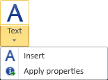
In the Annotate group, select Text > Insert.
-
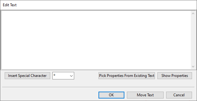
Pick the location where to add the text. The Edit Text dialog opens.
-
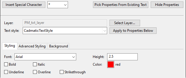
In the text pane, type the text to be inserted. The text is displayed on the drawing as you type.
If you need to insert special characters, use the Insert Special Character tool or paste a Unicode character from the clipboard, but be aware that not all fonts support all special characters.
-
Format the text as appropriate.
(Click Show Properties if the text properties are not visible in the dialog.)
-
You can pick all the properties from an existing text. To do this, click Pick Properties From Existing Text, pick the source text from the drawing, and press Enter.
-
You can select a predefined style from the Text style field and click Apply to Properties Below to apply the style to the text.
-
You can edit any of the text's properties manually.
-
-
You can move the text by clicking Move Text and picking the new location from the drawing.
Tip: While moving the text, you can rotate the text at 90° increments. Press the + (plus) key for counter-clockwise rotation and the = (equal) key for clockwise rotation, or select the respective command from the context menu.
-
Click OK.
-
Press Enter if you want to insert another text.
Apply properties
You can apply predefined properties to existing texts.
Do the following:
-
In the Annotate group, select Text > Apply properties.
-
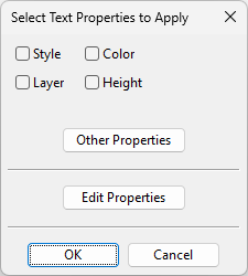
Pick one or more texts from the drawing and press Enter. The Select Text Properties to Apply dialog opens.
-
Select which properties to apply to the texts:
-
Style – Select this option to set the Text style field in the target text to the value currently defined in Text Properties. Note that this does not actually apply that style to the target text; you can apply the style later by opening the target text's properties and clicking Apply to Properties Below.
-
Layer – Select this option to set the Layer field in the target text to the value defined in Text Properties.
-
Color – Select this option to set the Color field in the target text to the value defined in Text Properties.
-
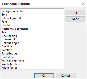
Other Properties – This button opens a list of all the properties you can select to be applied to the target text.
-
-
To review or edit the properties before applying them, click Edit Properties. For more information on these properties, see Text Properties.
-
Click OK.
Dimension
You can annotate drawings by showing any important dimensions such as lengths, distances, and angles.
You can insert and modify dimensions with the tools in the Dimension menu. You can also modify dimensions with the generic tools described in Modify.
Dimensions have the properties described in Dimension Properties. Administrator defines the default properties, but designers can override the defaults via Modify > Properties > Dimension properties when annotating a page or a view. The currently defined properties are used for all new dimensions, but they can also be applied to existing dimensions, as described in Apply properties. Moreover, the properties of an individual dimension can be changed without affecting any other dimension in the same document.
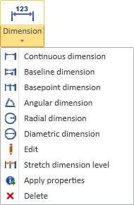
Continuous dimension | Baseline dimension | Basepoint dimension | Angular dimension from center point | Angular dimension from two lines | Radial dimension | Diametric dimension | Edit | Stretch dimension level | Apply properties | Delete
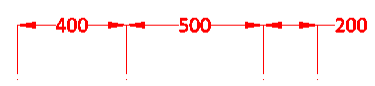
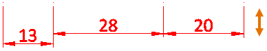
Continuous dimension
You can insert multiple dimensions so that each dimension line shows the measured distance as a stand-alone value, and each additional dimension line is placed end-to-end with the previous one.
Do the following:
-
In the Annotate group, select Dimension > Continuous dimension.
-
Insert the first dimension:
-
Pick the start point of the definition line.
-
Pick the end point of the definition line.
The dimension line and the measured distance are displayed and they move if you move the cursor.
-
Move the dimension line to a suitable distance from the definition line and pick that point.
-
-
You can add another dimension that starts from the end of the previous one and ends at the point you pick from the drawing.
-
Press Enter to stop adding dimensions to the same chain.
-
Press Enter again if you want to start a new insertion from a different start point.
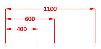
Baseline dimension
You can insert multiple dimensions so that all the dimension lines show the measured distance from the same baseline, and each additional dimension line is offset from the previous one.
Do the following:
-
In the Annotate group, select Dimension > Baseline dimension.
-
Insert the first dimension:
-
Pick the start point of the definition line.
-
Pick the end point of the definition line.
The dimension line and the distance from the baseline are displayed and they move if you move the cursor.
-
Move the dimension line to a suitable distance from the definition line and pick that point.
-
-
You can add another dimension that starts from the same baseline and ends at the point you pick from the drawing.
-
Press Enter to stop adding dimensions to the same chain.
-
Press Enter again if you want to start a new insertion from a different baseline.
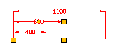
Basepoint dimension
You can insert multiple dimensions so that all the dimension lines show the measured distance from the same basepoint, and each additional dimension line is placed end-to-end with the previous one.

Do the following:
-
In the Annotate group, select Dimension > Basepoint dimension.
-
Insert the first dimension:
-
Pick the start point of the definition line.
-
Pick the end point of the definition line.
The dimension line and the distance from the basepoint are displayed and they move if you move the cursor.
-
Move the dimension line to a suitable distance from the definition line and pick that point.
-
-
You can add another dimension that starts from the end of the previous one and ends at the point you pick from the drawing.
-
Press Enter to stop adding dimensions to the same chain.
-
Press Enter again if you want to start a new insertion from a different basepoint.
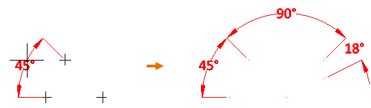
Angular dimension from center point
You can insert multiple dimensions that measure the angle between extension lines that start from a given centerpoint, so that each additional dimension line is placed at the same distance from the centerpoint as the first dimension line.
Do the following:
-
In the Annotate group, select Dimension > Angular dimension > from center point.
-
Pick the centerpoint to use for measuring one or more angles.
-
Pick the start point of the first extension line, and then pick the start point of the second extension line. The dimension displays the measured angle.
-
Move the dimension line to the intended location and pick that point.
-
You can add another dimension that starts from the previously inserted extension line and ends at the extension line whose end point you pick from the drawing.
-
Press Enter to stop adding dimensions to the same chain.
-
Press Enter again if you want to start a new insertion from a different centerpoint.
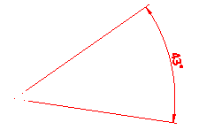
Angular dimension from two lines
You can insert a dimension that measures the angle between two lines.
Do the following:
-
In the Annotate group, select Dimension > Angular dimension > from two lines.
-
Pick the first and second point of the first line, then the first and second point of the second line. The dimension displays the measured angle.
-
Move the dimension line to the intended location and pick that point.
-
Press Enter to insert another dimension of the same type.
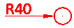
Radial dimension
You can insert a dimension to indicate the radius of an arc or circle
Do the following:
-
In the Annotate group, select Dimension > Radial dimension.
-
Select the arc or circle to be dimensioned, and press Enter.
-
Position the cursor at the desired location for the dimension text, then click or press Enter to confirm.
-
Press Enter again to insert another dimension of the same type.
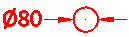
Diametric dimension
You can insert a dimension to indicate the diameter of an arc or circle
Do the following:
-
In the Annotate group, select Dimension > Diametric dimension.
-
Select the arc or circle to be dimensioned, and press Enter.
-
Position the cursor at the desired location for the dimension text, then click or press Enter to confirm.
-
Press Enter again to insert another dimension of the same type.
Edit
You can move the control points or modify the properties of an individual dimension.
Tip: You can use the Apply properties tool to apply properties to multiple dimensions at the same time.
Do the following:
-
In the Annotate group, select Dimension > Edit.
-
Pick the dimension to be edited. The dimension's editable points are displayed.
-
To move any of the points, pick the point, move the point, and pick the new location to accept the move.
-
To edit the dimension's properties, right-click the view and select Modify properties from the context menu.
-
Press Enter to accept the changes.
-
Press Enter again if you want to edit another dimension.
Stretch dimension level
You can adjust the distance between the dimension line and its definition line.
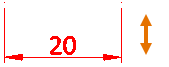
When several dimension lines form a chain, you can stretch all of them at the same time (default) or exclude some of them from the stretch operation.
Do the following:
-
In the Annotate group, select Dimension > Stretch dimension level.
-
Pick the dimension to be stretched.
-
If the dimension contains dimension lines that should stay where they are, select Modify set (P), click the lines that are not be stretched, and press Enter to accept the set.
-
Drag the mouse to move the dimension lines, and pick the intended new location.
-
Press Enter if you want to stretch another dimension.
Apply properties
You can apply predefined properties to existing dimensions.
Do the following:
-
In the Annotate group, select Dimension > Apply properties.
-
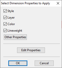
Pick the dimensions to which to apply the properties and press Enter. The Select Dimension Properties to Apply dialog opens.
-
All Dimension Properties are selected by default; change the selections if appropriate.
-
To modify individual properties, click Edit Properties to modify them, and then Other Properties to apply them.
-
Click OK.
Delete
You can delete dimensions.
Do the following:
-
In the Annotate group, select Dimension > Delete.
-
Pick the dimensions to be deleted and press Enter.
Label
You can annotate drawings by inserting labels that provide information about the model objects such as their position ID or location in the model. Labels can also be used for adding document-related information such as page numbers.
You can insert and modify labels using the tools found in the Label menu. You can also modify labels with the generic tools described in Modify.
Labels have the properties described in Label Properties. Designers can define the properties via Modify > Properties > Label properties when annotating a page or a view. The currently defined properties are used for all new labels, but they can also be applied to existing labels, as described in Apply properties. Moreover, the properties of an individual label can be changed without affecting any other label in the same document.
Note: These commands are disabled when the Annotating field is set to "Page".
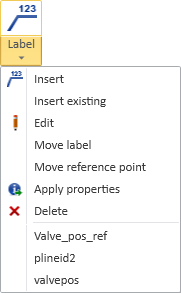
Insert | Insert existing | Edit | Move label | Move reference point | Apply properties | Delete | Recently used labels
Insert
You can annotate drawings by inserting labels. You are prompted to select the label definition to use.
Do the following:
-
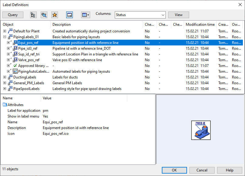
In the Annotate group, select Label > Insert. The Label Definition dialog opens, listing the available label definitions.
-
Select the label definition to use and click OK.
-
Pick the object to be labeled. If the label requires a reference point, move the cursor to where you want the reference point to be. Then press Enter.
-
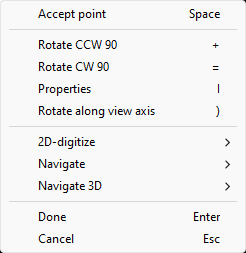
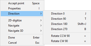
You can use context-menu commands to rotate the label.
-
Rotate CCW 90 + Rotates the label 90 degrees counterclockwise.
-
Rotate CW 90 = Rotates the label 90 degrees clockwise.
-
Properties I Allows precise rotation through the Label text properties dialog.
-
Rotate along view axis ) If enabled, the CCW and CW commands align the label to the drawing view's closest coordinate axis instead of the sheet's X/Y axes. This option is only available in axonometric views.
-
-
Move the new label to the intended location and pick that point.
-
You can continue picking objects and inserting labels of this kind or press Enter to exit the tool.
-
Press Enter again if you want to restart the tool and select a different kind of label.
Insert existing
You can insert labels by picking the label definition and the properties of the label text or label symbol from an existing label.
Do the following:
-
In the Annotate group, select Label > Insert existing.
-
Pick an existing label whose appearance you want to apply to the new label.
-
Pick the object to be labeled. If the label requires a reference point, move the cursor to where you want the reference point to be. Then press Enter.
-
Move the new label to the intended location and pick that point.
-
You can continue picking objects and inserting labels of this kind or press Enter to exit the tool.
-
Press Enter again if you want to restart the tool and select a different kind of label.
Edit
You can edit existing labels.
Do the following:
-
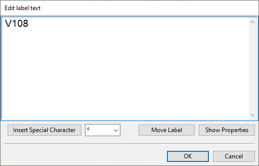
In the Annotate group, select Label > Edit. The Edit label text dialog opens.
-
Edit the label text or the label properties described in Label Properties as appropriate and click OK.
-
Press enter if you want to pick another label and edit it.
Move label
You can move a label text to a different location. The reference line is automatically adjusted to match the new position of the label. The reference point is not moved.
Do the following:
-
In the Annotate group, select Label > Move label.
-
Pick the label to be moved.
-
Drag the mouse to move the label to the intended location and pick that point.
-
You can move another label in the same way or press Enter to exit the tool.
Move reference point
You can move the reference point of an existing label to a different location. The label itself is not moved.
Do the following:
-
In the Annotate group, select Label > Move reference point.
-
Pick the label whose reference point you want to move.
-
Drag the mouse to move the reference point to the intended location and pick that point.
-
You can move another label's reference point in the same way or press Enter to exit the tool.
Apply properties
You can apply predefined properties to existing labels.
Do the following:
-
In the Annotate group, select Label > Apply properties.
-
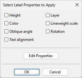
Pick the labels to which to apply the properties and press Enter. The Select Label Properties to Apply dialog opens.
-
Select which properties to apply. For more information on these properties, see Label Properties.
-
To review or edit the properties before applying them, click Edit Properties.
-
Click OK.
Delete
You can delete labels.
Do the following:
-
In the Annotate group, select Label > Delete.
-
Pick the labels to be deleted and press Enter.
Recently used labels
The Labels menu lists up to eight recently used label types, allowing for easy insertion of frequently used labels. You can start inserting labels of a specific type into the active drawing view simply by selecting the label type from the list.
Symbol
You can annotate drawings by inserting 2D symbols.
You can insert and modify symbols with the tools in the Symbol menu. You can also modify symbols with the generic tools described in Modify.
Symbols have the properties described in Symbol Properties. Administrator defines the default properties, but designers can override the defaults via Modify > Properties > Symbol properties when annotating a page or a view. The currently defined properties are used for all new symbols, but they can also be applied to existing symbols, as described in Apply properties. Moreover, the properties of an individual symbol can be changed without affecting any other symbol in the same document.
Insert
You can annotate drawings by inserting 2D symbols.
Do the following:
-
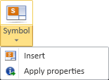
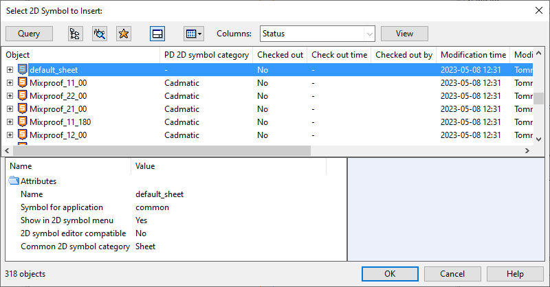
In the Annotate group, select Symbol > Insert. The Select 2D Symbol to Insert object browser dialog opens.
-
Select the symbol to be inserted and click OK.
-
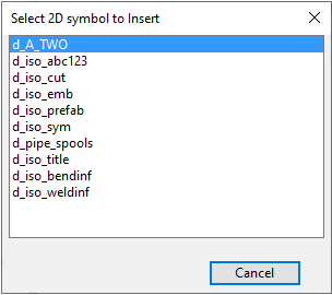
If the 2D symbol script defines multiple symbols, a secondary dialog opens. Click the name of the required symbol.
-
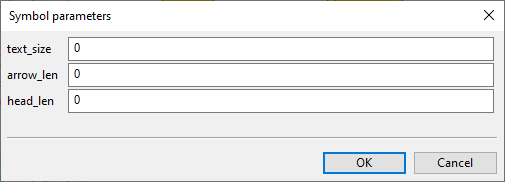
If the symbol requires parameters, the Symbol parameters dialog opens. Enter the required parameters and click OK.
-
Move the symbol to the intended location. While moving the symbol, you can right-click the view to open the context menu which allows you to rotate the symbol or access the symbol properties.
-
Pick the origin point where to add the symbol.
-
Press Enter if you want to insert another symbol.
Apply properties
You can apply predefined properties to existing 2D symbols.
Do the following:
-
In the Annotate group, select Symbol > Apply properties.
-
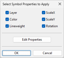
Pick the symbols to which to apply the properties and press Enter. The Select Symbol Properties to Apply dialog opens.
-
All properties are selected by default; change the selections if appropriate. For more information on these properties, see Symbol Properties.
-
To review or edit the properties before applying them, click Edit Properties.
-
Click OK.
Section markers
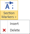
You can annotate drawings by inserting section markers that indicate the beginning of a section that is shown in another view.
You can create and delete section markers with the tools in the Section markers menu. You can modify symbols with the generic tools described in Modify. The texts are edited as normal drafting text, the section lines are edited as line objects, and the direction arrows are 2D symbols whose properties you can change via the Parameters context-menu command.
Section markers have the properties described in Section Marker Properties. Administrator defines the default properties, but designers can override the defaults via Modify > Properties > Section markers when annotating a page or a view. The currently defined properties are used for all new section markers. Moreover, the properties of an individual section marker can be changed without affecting any other section marker in the same document.
Note: Unlike other drafting object types, section markers have no tool for applying the current section marker properties to existing section marker objects. Also, using the set operation tool Modify > Properties > Apply properties described in Objects in a set will apply default text properties, default line properties, and default symbol properties if you select the respective elements from a section marker.
Tip: On the Home tab, you can create a section marker and a section view at the same time, as described in Section view.
Insert
You can annotate drawings by inserting section markers.
Do the following:
-
In the Annotate group, select Section markers > Insert.
-
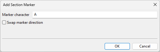
Pick the left end of the section marker and the right end of the section marker from the drawing. The Add Section Marker dialog opens.
-
Fill in the following information:
-
Enter the text to display in the section marker.
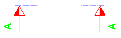
-
If the section marker arrows are pointing to the wrong direction, select the Swap marker direction option to switch the direction.
-
Click OK.
-
-
Press Enter if you want to insert another section marker.
Delete
You can delete section markers. This deletes all the elements of the section marker.
Tip: You can use the generic Delete tool to remove individual elements from a section marker.
Do the following:
-
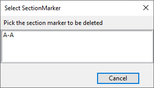
In the Annotate group, select Section markers > Delete. The Select SectionMarker dialog opens, listing the section markers in the document.
-
Select the section marker to be deleted.
Hatch plate face
You can add a hatch pattern to a plate face. You can use this, for example, to hatch the footbridges of a process plant.
Note: These commands are not available when the Annotating field is set to 'Page'.
Hatch plate face | Apply properties
Hatch plate face
You can generate a 2D hatch to the face of a visible, opaque 3D object. The target object must be of type Structural Component, Equipment, or Hull Construction Part, and the component model must not contain any other primitive types than Sweep, Plate, or BSV; for more information on primitives, see Primary primitives.
The boundaries of 2D hatches are not associative. If the hatched area changes in the 3D model, the hatch must be re-created by deleting the existing hatch and inserting a new one.
Do the following:
-
In the Annotate group, click the hatch insertion tool
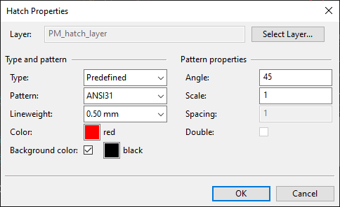
 or select Hatch Plate Face > Hatch plate face. The Hatch Properties dialog opens.
 -
Define the hatch properties. For more information on these properties, see Hatch Properties.
-
Click OK.
-
Select the plate face. All visible parts of the selected plate face are hatched.
-
Press Enter if you want to insert another hatch.
Apply properties
You can apply predefined properties to existing plate face hatches.
Do the following:
-
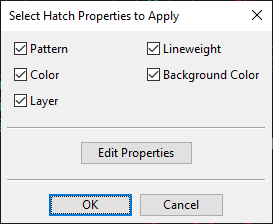
In the Annotate group, select Hatch Plate Face > Apply properties.
-
Pick the hatches to which to apply the properties and press Enter. The Select Hatch Properties to Apply dialog opens.
-
All properties are selected by default; change the selections if appropriate. For more information on these properties, see Hatch Properties.
-
To review or edit the properties before applying them, click Edit Properties.
-
Click OK.